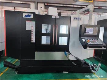
Calibrating a heavy duty CNC vertical milling machine is a crucial process that ensures the machine operates with high precision and accuracy. As a supplier of Heavy Duty CNC Vertical Milling Machines, I understand the significance of proper calibration in achieving optimal performance and producing high - quality parts. In this blog, I will guide you through the step - by - step process of calibrating a heavy duty CNC vertical milling machine.
Pre - calibration Preparations
Before starting the calibration process, it is essential to make some preparations. First, ensure that the machine is clean. Remove any chips, debris, or coolant from the worktable, spindle, and other components. A clean machine not only helps in accurate calibration but also extends the machine's lifespan.
Next, check all the mechanical components for wear and tear. Inspect the ball screws, linear guides, and bearings. Worn - out components can significantly affect the machine's accuracy. If any components are found to be damaged, they should be replaced before calibration.


It is also important to check the electrical connections. Loose or faulty electrical connections can lead to erratic machine behavior and inaccurate calibration. Make sure all cables are properly plugged in and there are no signs of damage.
Checking the Machine Level
The first step in the calibration process is to check the machine's level. An unlevel machine can cause uneven wear on the components and lead to inaccurate machining. Use a high - precision spirit level to check the level of the worktable in both the X and Y axes.
Place the spirit level on the worktable and adjust the machine's leveling feet until the bubble in the spirit level is centered. It may be necessary to make small adjustments to the leveling feet and re - check the level multiple times to achieve an accurate result. A properly leveled machine provides a stable base for accurate machining.
Spindle Runout Calibration
The spindle runout is a critical factor in the performance of a CNC vertical milling machine. Runout refers to the deviation of the spindle's rotation from its ideal axis. Excessive runout can cause poor surface finish, inaccurate hole diameters, and reduced tool life.
To measure the spindle runout, use a dial indicator. Mount the dial indicator on the machine's worktable or a stable fixture and position the probe against the spindle nose. Rotate the spindle slowly by hand and observe the reading on the dial indicator. The maximum variation in the reading is the spindle runout.
If the runout exceeds the manufacturer's specifications, it may be necessary to adjust the spindle bearings or replace worn - out components. In some cases, the spindle may need to be realigned. Consult the machine's manual or contact a professional technician for guidance on spindle runout adjustment.
Axis Straightness and Perpendicularity Calibration
The straightness and perpendicularity of the machine's axes are essential for accurate machining. To check the straightness of the X and Y axes, use a laser interferometer. A laser interferometer is a highly accurate measuring device that can detect even small deviations in the axis movement.
Mount the laser interferometer on the machine and align it with the axis to be measured. Move the axis along its full travel and record the readings from the interferometer. The straightness error should be within the manufacturer's specified tolerance. If the error exceeds the tolerance, the axis may need to be adjusted or the linear guides may need to be realigned.
To check the perpendicularity between the X and Y axes, use a square. Place the square on the worktable and align it with one of the axes. Then, check the alignment of the other axis against the square. Any deviation from 90 degrees indicates a perpendicularity error. Similar to the straightness calibration, if the perpendicularity error is out of tolerance, adjustments need to be made.
Backlash Calibration
Backlash is the clearance between the mating components in the machine's drive system, such as the ball screw and nut. Excessive backlash can cause positioning errors and affect the accuracy of the machining. To measure the backlash, use a dial indicator.
Mount the dial indicator on the machine and position the probe against a fixed point on the axis. Move the axis in one direction and then reverse the direction. The difference in the position reading when the direction is reversed is the backlash.
To reduce backlash, adjust the pre - load on the ball screw nut. This can usually be done by adjusting the nut's pre - load spring or by using a pre - loaded ball screw assembly. Some machines also have software - based backlash compensation features that can be used to correct for small amounts of backlash.
Tool Length and Diameter Calibration
Proper tool length and diameter calibration are essential for accurate machining. Incorrect tool length can cause depth of cut errors, while incorrect tool diameter can lead to dimensional inaccuracies in the machined parts.
To calibrate the tool length, use a tool setter. A tool setter is a device that measures the length of the tool from the spindle nose to the tool tip. Mount the tool in the spindle and position it in the tool setter. The tool setter will automatically measure the tool length and transmit the data to the machine's control system.
For tool diameter calibration, use a tool measuring device such as a micrometer or a laser - based tool measuring system. Measure the diameter of the tool at multiple points along its length to ensure accuracy. Enter the measured tool diameter into the machine's control system.
Software and Parameter Calibration
In addition to the mechanical and physical calibrations, the machine's software and parameters also need to be calibrated. Check the machine's control system for any error messages or warnings. Update the control system software to the latest version to ensure compatibility and optimal performance.
Review the machine's cutting parameters, such as feed rate, spindle speed, and depth of cut. These parameters should be set according to the material being machined, the tool being used, and the desired surface finish. Incorrect cutting parameters can lead to poor machining results and increased tool wear.
Post - calibration Verification
After completing all the calibration steps, it is important to verify the calibration results. Run a test program on the machine to machine a simple part. Measure the dimensions of the machined part using a high - precision measuring device such as a coordinate measuring machine (CMM).
Compare the measured dimensions with the design dimensions. If the dimensions are within the specified tolerance, the calibration is successful. If there are still significant errors, re - check the calibration steps and make any necessary adjustments.
Conclusion
Calibrating a heavy duty CNC vertical milling machine is a complex but essential process. By following the steps outlined in this blog, you can ensure that your machine operates with high precision and accuracy. As a supplier of Heavy Duty CNC Vertical Milling Machines, we offer a range of products such as the VMC 850, Small Shop Cnc Milling Machine, and CNC Metal Milling Machine.
If you are interested in purchasing a heavy duty CNC vertical milling machine or need further assistance with calibration, please feel free to contact us for procurement and negotiation. We are committed to providing high - quality machines and excellent after - sales service.
References
- CNC Milling Machine Operation Manuals
- Precision Measuring Instrumentation Guides
- Machining Technology Handbooks