


3 axis cnc vertical machining center
Dongguan Jide Precision Machinery Technology Co., Ltd. is one of the most credible manufacturers and suppliers of 3 axis cnc vertical machining center in China. If you're going to wholesale high quality 3 axis cnc vertical machining center made in China, welcome to get quotation and free sample from our factory. All customized products are with high quality and competitive price.
3 axis cnc vertical machining center how to design the inclined top of the mold?
Use of inclined roof
The inclined top mechanism is generally used to form the product's internal or external undercuts, and can not be directly molded with the movable mold side slider, and also plays the role of ejecting the product.
General structure and category of inclined roof
The inclined roof is generally composed of two parts: the body part and the forming part. It is the same as the slider. Due to whether the body part and the forming part are combined, the inclined roof can be classified into: integral inclined roof (also called non-combined inclined roof) and non-integrated inclined roof (also called combined inclined roof) .
Note that because the inclined roof is relatively small, generally we use the integral inclined roof, and rarely use the combined inclined roof. The integral inclined roof has a compact structure, good strength and no room for damage. As for the larger inclined roof, the combined type can be used in the design, which is more convenient to replace, easy to repair and maintain, and the processing is relatively simple.
In addition, due to the different positioning structure of the bottom end of the inclined roof body, the inclined roof can be classified into: cylindrical pin inclined roof and T-block inclined roof. For these two kinds of inclined roofs, cylindrical pin inclined roofs are in the design There are many applications, the main reason is that it is easy to process, easy to install and maintain. The T-block inclined top is mainly used for larger products with higher precision requirements. It also needs to be matched with a special T-shaped base, which is difficult to process and cooperate, and the manufacturing cost will increase.
The movement principle of the inclined roof
The inclined roof is placed in the inclined hole of a fixed template, and the inclined roof matches the inclined hole. After giving the inclined roof a thrust from the bottom to the top to push the inclined roof upward for a certain distance, it was found that under the forced action of the inclined hole and the thrust, the inclined roof not only moved upward, but also moved a certain distance to the inclined direction of the inclined roof (as shown in the figure) Position gap). During the ejection process, since the product moves in a vertical line, the inclined top not only moves in the vertical line, but also moves in the opposite direction to the dead angle, so that the dead angle can be dealt with.

Main points of inclined roof design
(1) Determine the angle of the sloping top according to the actual stroke H, generally 3~12°, and the slope should be as small as possible; the core pulling distance of the sloping top is generally greater than the product core pulling distance 3mm; the strength of the sloping top, the slope of the sloping top and The ejection distance should be coordinated;
(2) Determine the width of the inclined top according to the width of the product buckle;
(3) Determine the thickness of the inclined roof according to the width of the inclined roof and the product position of the inclined roof (mainly depending on whether there is interference and whether the gap of the glue level on the inclined roof is large), generally not less than 6.0;
(4) Determine the form of the guide chute according to the size, thickness and total length of the inclined roof. The guide chute is generally made of 40Cr material;
(5) Design the guide block according to the size of the inclined top; the material is generally 40Cr, bronze;
(6) H13 shall be used for all inclined roof materials, and be nitrided;
(7) The inclined roof needs to be processed with oil grooves (except the top and bottom surfaces of the inclined roof);
(8) Pay attention to the placement direction of the finished product, avoid hanging the inclined roof, and increase the accelerating roof when necessary;
(9) When drawing, the inclined top should be expressed in three views;
(10) The top surface of the inclined top is lower than the product surface by 0.05mm to avoid straining the surface;
(11) It is necessary to consider whether the product will stick to the sloping top, and whether there is positioning to pull the product;
(12) It is necessary to check whether the head of the inclined top is reverse inclined (the ejection will shovel glue), and pay attention to whether the inclined top will interfere with other parts (such as other inclined tops, thimble, bone position), must be checked;
(13) When the product is very deep and there is a sloped top on the side, the sloped top should be positioned by a step. There is also a situation where the sloped top is on the side of the product (the product has a certain depth), and the sloped top has a deeper side Bone position.
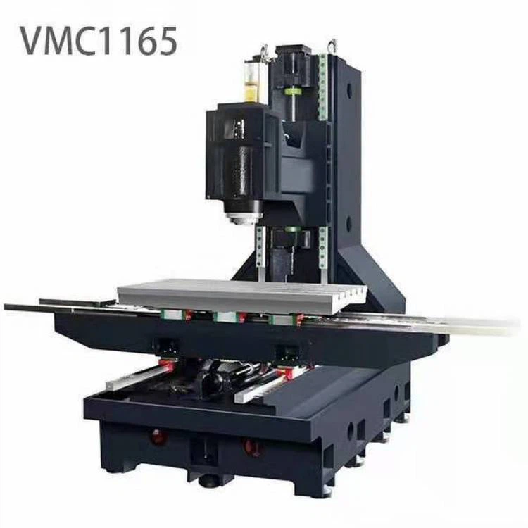
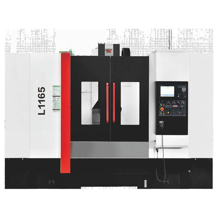
3 axis cnc vertical machining center feature:
1. The roller linear rail has high rigidity, high speed and high precision, and the three-axis moving speed is 36 meters.
2. High rigidity Taiwan ROYO short nose spindle 10000/12000/15000 direct-connected spindle
3. Spindle ring spray, air pressure seal, slag flushing in the water pan, oil-water separation tank 4. The system can be equipped with Mitsubishi 80B/fanuc -OI--MF
5. Taiwan 24T/32T tool magazine can be equipped according to customer needs
Details pictures

 3 axis cnc vertical machining center description
1.1 Technical characteristics
The high-speed vertical machining center adopts a Japanese imported control system (Mitsubishi or Fanuc) and its supporting servo drives and motors to realize three-axis linkage. It is suitable for parts with appropriate batches that are complex, multi-process, high-precision requirements, multiple types of ordinary machine tools, various tools and tooling, and multiple clamping and adjustments to complete the processing. Mainly process box parts, complex curved surfaces, special-shaped parts, plates, sleeves, and plate parts. It is widely used in products in the fields of electronics, machinery, automobiles, airplanes, aerospace, ships, and national defense.
Whole machine structure: The main parts of the machine body are made of high-quality cast iron, the internal ribs and bones are strengthened, all are tempered, and the finite element analysis is carried out by special design software. It has the characteristics of high strength, good stability, and resistance to deformation, ensuring the whole machine The rigidity and accuracy stability of long-term use.
Spindle: Box-shaped spindle head structure, internal ribs and bones strengthened, P4 grade ultra-precision angular ball bearing and large span support design, so that the spindle can withstand strong radial and axial thrust, and eliminate vibration caused by heavy load cutting.
Equipped with Taiwan brand spindle, direct connection and belt connection are available (direct connection spindle above 12000 rpm). The nose end of the spindle is designed to be dustproof with the spindle air curtain, which can prevent debris from entering, ensuring the accuracy and life of the spindle.
The imported oil cooler reduces the temperature of the main shaft, improves the service life of the bearing, and reduces the influence of the thermal deformation of the main shaft on the machining accuracy.
Transmission components: adopt precision bearings and Taiwan Yintai high-quality precision ball screws. The ball screw installation adopts the pre-stretching process, which improves the rigidity of the transmission components while eliminating the ball screw elongation caused by the thermal stress effect during the temperature rise of the ball screw during operation, which improves the accuracy of the machine tool during long-term use. Sex.
Linear rail: The three-axis adopts linear roller rail design, which has the characteristics of high rigidity, high wear resistance, high precision, etc., and has high processing stability.
System: Equipped with high-performance FANUC or Mitsubishi CNC system to ensure the stability of machine tool control, as well as the CNC machining functions and auxiliary functions required by users.
Drive: The three coordinate axes of X, Y and Z all use Japanese Mitsubishi or FANUC motors, which have the characteristics of good control characteristics, large torque, good following accuracy, fast response, and good stability.
Lubrication: The guide rail and ball screw adopt a centralized automatic lubrication system, which can regularly and quantitatively inject oil into each lubrication part to ensure uniform lubrication of each moving surface, effectively reducing frictional resistance, improving movement accuracy, and ensuring the use of guide rails and ball screws life.
Machine tool protection: The machine tool adopts fully enclosed protection to ensure the personal safety of the staff during the processing, and the coolant and iron filings during the processing are safely and fully recovered to ensure a clean and tidy workplace. The machine tool guide rail is protected by a stainless steel telescopic shield, which has the characteristics of good protection performance and long service life, which can effectively prevent iron filings and coolant from entering the machine tool to damage the guide rail and lead screw. The electric control box adopts a fully sealed design, and the heat exchanger dissipates heat, which ensures the cleanliness of the electric control box and the service life of electrical components.
Quality Assurance: When the fuselage is assembled, each process is quality controlled according to the national standard tolerance, which effectively reduces the deviation of the whole machine caused by the accumulated error. After the system is assembled, perform 72-hour copy machine operation to monitor various indicators such as noise, vibration, rapid movement, and tool change. Advanced instruments such as laser interferometer, ball bar, dynamic balancer and three-coordinate measuring instrument are used to test the machine tool to carry out part trial processing testing, heavy cutting testing, and rigid tapping testing to ensure that each performance meets the factory's high-quality standards.
The safety design of the machine tool complies with the relevant regulations of GB15760-2004 "General Technical Conditions for Safety Protection of Metal Cutting Machine Tools", and its geometric accuracy standard complies with JB/T8771.2-1998 "Machining Center Inspection Conditions Part 2: Vertical Machining Center Geometric Accuracy Inspection" And JB/T8771.4-1998 "Machining Center Inspection Conditions Part 4: Linear and Rotary Axis Positioning Accuracy and Repeated Positioning Accuracy Inspection".
Parameters

3 axis cnc vertical machining center common enquiries
Use environment
The environmental operating temperature of the equipment: 10℃~40℃.
The relative humidity of the operating environment: should be controlled within 75%.
The equipment should avoid radiation and vibration from other high heat sources to avoid machine tool failure or loss of machine accuracy.
power supply
Voltage: 3-phase, 380V, voltage fluctuation within ±10%, power frequency: 50HZ. (According to customer requirements)
If the voltage in the application area is unstable, the machine tool should be equipped with a regulated power supply to ensure the normal operation of the machine tool.
Air pressure
In order to ensure the normal working performance of the equipment, if the compressed air of the air source does not meet the air source requirements, a set of air source purification devices (dehumidification, oil removal, filtration) should be added before the machine's air intake.
Grounded
The machine tool should have a reliable grounding: the grounding wire is a copper wire, the wire diameter should not be less than 10mm2, and the grounding resistance is less than 4 ohms.
The ground wire of each CNC machine tool should be connected to a separate ground rod. Grounding method: drive a copper rod with a diameter of about Φ12mm into the ground 1.8~2.0m, and the ground wire (the diameter of the wire is not less than the diameter of the power cord) must be reliably connected to the ground rod with screws.

Hot Tags: 3 axis cnc vertical machining center, China, suppliers, manufacturers, factory, price, for sale, made in China, Best Vertical Machining Center, 5 Axis Cnc Machining Center
You Might Also Like



Send Inquiry