


CNC Milling Machine Near
Y axis travel mm 710
Z-axis travel mm 710
Spindle nose to work surface mm 110-810
Spindle center to column guide mm 792
work table
Table Dimensions (L x W) mm 1300*700
T-slot (number-size*spacing) mm 5*18X125
maximum load Kg 1200
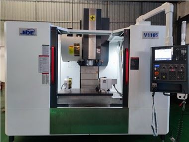
Dongguan Jide Precision Machinery Technology Co., Ltd. is one of the most credible manufacturers and suppliers of cnc milling machine near in China. If you're going to wholesale high quality cnc milling machine near made in China, welcome to get quotation and free sample from our factory. All customized products are with high quality and competitive price.


V1270 application and features:
1. Three-axis rail, fast positioning, meeting the requirements of high-speed and high-precision processing.
2. Wide base, herringbone-shaped large-span column, strong rigidity and high stability.
The maximum spindle speed is 10,000 rpm, and the processing finish is high.
The standard configuration
1>. MITSUBISHI M80B, Celeron panel wire 1 set
2>. Belt-type spindle BT40-10000 rpm 1 set
3>. Spindle oil cooler 1 set
4>. Rear flushing chip removal-front discharge outlet 1 set
5>. Automatic lubrication system 1 set
6>. Foundation screws and pads 10 sets
7>. Tool box 1 set
8>. Work lights (explosion-proof lights) 2 sets
9>. Warning lights 1 set
10>. Spindle air blowing device 1 set
11>. Fully enclosed protective cover 1 set
12>. Automatic power-off system 1 set
13>. Cooling water system 1 set
14>. Air gun 1 set
15>. Rigid tapping function standard configuration
16>. Electrical box heat exchanger 1 set
17>. "Program Manual", "Operation Manual"/U disk data 1 set
18: Export packaging: including wooden pallet + vacuum packaging + forklift loading
|
Parameter |
Unit |
V-1270 |
||
|
● |
TRAVEL |
|
|
|
|
X-axis travel |
mm |
1200 |
||
|
Y axis travel |
mm |
710 |
||
|
Z-axis travel |
mm |
710 |
||
|
Spindle nose to work surface |
mm |
110-810 |
||
|
Spindle center to column guide |
mm |
792 |
||
|
● |
work table |
|
|
|
|
Table Dimensions (L x W) |
mm |
1300*700 |
||
|
T-slot (number-size*spacing) |
mm |
5*18X125 |
||
|
maximum load |
Kg |
1200 |
||
|
L |
Spindle |
|
|
|
|
Spindle speed |
rpm |
10000 |
||
|
Spindle motor power |
kw |
11/15 |
||
|
Spindle taper hole (model/installation size) |
BT40(150) |
|||
|
● |
feed |
|
|
|
|
G00 rapid traverse (X axis) |
m/min |
36 |
||
|
G00 rapid traverse (Y axis) |
m/min |
36 |
||
|
G00 rapid traverse (Z axis) |
m/min |
36 |
||
|
● |
machine precision |
|
|
|
|
positioning accuracy |
mm |
0.005/300 |
||
|
Repeatability |
mm |
0.003/300 |
||
|
● |
other |
|
|
|
|
Floor space (length) |
mm |
4100 |
||
|
(width) |
mm |
3100 |
||
|
Machine height (height) |
mm |
3200 |
||
|
machine weight |
Kg |
7000KGS |
||
|
vacuum packaging |
/ |
YES |
||
|
Fixed wooden frame |
/ |
YES |
||
|
Item |
Brand |
Origin |
|
Controller |
MITSUBISHI M80B |
JAPAN |
|
Spindle motor |
11KW 57NM |
JAPAN |
|
X, Y, Z axis motors X-axis motor 1FK7084-3BC71-1RG1 Y-axis motor 1FK7084-3BC71-1RG1 Z-axismotor 1FK7084-3BC71-1RG1/brake Z |
HG303/HG303/HG303 |
JAPAN |
|
handwheel |
TOSUKO |
Japan 5v |
|
Tool magazine BT40-24T with bracket |
SANJET/AIMACH |
TAIWAN |
|
Spindle BT40-150-10000 (belt type) |
WAY LONG/Royal/KENTURN |
TAIWAN |
|
Spindle oil cooler Condensation 10A |
RUCOL |
China |
|
Roller screw (X, Y, Z) 4012 C3 grade |
Extended double nut HIWIN C3 class |
TAIWAN |
|
Linear rail (roller) XZ 45 roller RGH45 P grade |
HIWIN/PMI |
TAIWAN |
|
Linear rail (roller) Y 45 roller RGH45 P grade 2 rails |
HIWIN/PMI |
Japan |
|
Bearing 30TAC (3062) P4 |
NSK/FAG |
domestic |
|
Coupling MJC-65CS-EGR-24-35 |
DK |
joint venture |
|
Oiler Lubrication pump 3L with microcomputer |
Baotn |
domestic |
|
Heat exchanger oil cooler 220V air cooling |
SINAER |
domestic |
|
Cutting water motor 750W 220V/380V |
SMC |
Japan |
|
Solenoid valve 24V/2 sets |
SMC |
Japan |
|
Air filter 2 filter cups 6PAM |
Schneider |
France |
|
AC contactor 220V |
Schneider |
France |
|
Overload protector |
Schneider |
France |
|
Relay |
HEYI |
joint venture |
|
Machine tool work light (explosion-proof light) |
BEIZHE |
joint venture |
|
Other main electrical components |
HONGWANG |
domestic |
|
Shields (X, Y, Z) |
Domestic special grade paint |
Roller guide rails and ball guide rails are actually linear guide rails. Roller guide rails have their own advantages, so they can become an independent category of linear guide rails and occupy a sufficient share in the market. Then I will introduce them to you below. Advantages of roller guides!
1. The roller guide is a type of linear guide that reduces the friction coefficient by converting sliding friction into rolling friction, which can further increase its flexibility.
2. The roller guide has a high degree of precise positioning, and some models can reach a repeatable positioning accuracy of 0.2 μm, so it can be used in high-precision machine tools and automation equipment.
3. The loss of the roller guide rail is small, mainly because its friction coefficient is extremely low, so the mutual wear between the rollers and the guide rail is small, thus ensuring its service life.
4. The large load capacity is the most significant advantage of roller guides. They are often used in automated equipment such as automatic assembly machines, heavy-duty handling equipment, CNC processing equipment, cutting processing equipment, grinders, forming machines, various gantry machine tools, etc.
To sum up, the above are some of the characteristics and advantages of roller guides.


Comparison of application occasions
The large machining center is mainly used for the processing of box-type and complex curved surface parts. It can concentrate the functions of milling, boring, drilling, thread processing, etc. on one device. Because it has a variety of tool changing or tool selection functions and an automatic table exchange device (APC), the parts can automatically complete or nearly complete all processing procedures on all sides of the parts after one clamping, greatly improving production efficiency.
CNC Milling machine near has a body that is integrally cast and has high spindle rigidity. It is suitable for completing workpieces or mold processing with a large amount of milling. It can also perform roughing or finishing on large molds and materials with relatively high hardness.


I. CNC Milling machine near Operation preparation
1.1 Check the oil level in the oil tank and whether the oil is deteriorated or contaminated.
1.2 Check whether the cooling pump filter is blocked.
1.3 Check whether the ball screw is lubricated enough; whether the fan is rotating; whether the motor is vibrating or heating; whether the cable is aging and cracked.
1.4 Only employees who have participated in the training and passed the examination can work on the job. No one else can operate without permission.
1.5 After each start-up or emergency stop reset of the machine tool, first return the machine tool to the reference zero position (i.e. return to zero) so that the machine tool has a reference position for its subsequent operation.
II. Operation
2.1 Clamping the workpiece
2.1.1 Before clamping the workpiece, clean all surfaces first, and do not allow oil, iron filings and dust to stick to them, and use a file (or oilstone) to remove burrs on the surface of the workpiece.
2.1.2 The equal height iron used for clamping must be ground by a grinder to make it smooth and flat. The shims and nuts must be strong and can reliably clamp the workpiece. Some small workpieces that are difficult to clamp can be clamped directly on the vise.
2.1. 3 Make sure that the machine tool workbench is clean and free of iron filings, dust, and oil.
2.1. 4 Shims are generally placed at the four corners of the workpiece. For workpieces with too large a span, shims of equal height must be placed in the middle.
2.1. 5 According to the dimensions of the drawing, use a ruler to check whether the length, width, and height of the workpiece are qualified.
2.1. 6 When clamping the workpiece, according to the clamping and placement method in the programming work manual, consider avoiding the processing area and the situation where the tool head may hit the fixture during processing.
1, 2.1. 7 After the workpiece is placed on the pad, the workpiece reference surface should be checked according to the requirements of the drawing. The error of the workpiece base angle surface reading should be less than 0.01mm, the top surface X, Y and Z vertical direction workpiece size within 100mm error is less than 0.01mm, the workpiece size above 600mm error is less than 0.05mm. For the workpiece that has been ground on all six sides, its verticality should be checked to see if it is qualified.
2.1. 8 After the workpiece is checked, the nut must be tightened to prevent the workpiece from shifting during processing due to loose clamping.
2.1. 9 Check the table again to make sure that the error does not exceed the tolerance after clamping.
2. 2 Workpiece touch count: The clamped workpiece can be touched by a touch head to determine the reference zero position of the processing. The touch head can be photoelectric or mechanical. There are two touch selection methods: center touch count and single-side touch count. The center touch count steps are as follows:
2.2. 1 Touch counting method: mechanical speed 450~600rpm.
2.2.2 Manually move the X axis of the worktable to make the touch counting head touch one side of the workpiece. When the touch counting head just touches the workpiece, set the relative coordinate value of this point to zero; then manually move the X axis of the worktable to make the touch counting head touch the other side of the workpiece. When the touch counting head just touches the workpiece, record the relative coordinate at this time.
2.2.3 Subtract the diameter of the touch counting head (i.e. the length of the workpiece) from its relative value to check whether the length of the workpiece meets the requirements of the drawing.
2.2.4 Divide this relative coordinate number by 2, and the resulting value is the middle value of the workpiece X axis. Then move the worktable to the middle value on the X axis, set the relative coordinate value of the X axis of this point to zero, and this point is the zero position on the X axis of the workpiece.
2.2. 5 Carefully record the mechanical coordinate value of the zero position on the X axis of the workpiece in one of G54~G59, and let the machine tool determine the zero position on the X axis of the workpiece. Carefully check the correctness of the data again.
2.2.6 The steps for setting the zero position of the Y axis of the workpiece are the same as those for the X axis.
2.3 Prepare all tools according to the programming operation manual.
2.4 According to the tool data in the programming operation manual, replace the tool to be processed, let the tool touch the reference surface, and set the relative coordinate value of this point to zero.
2.5 Move the tool to a safe place, manually move the tool down 50mm, and set the relative coordinate value of this point to zero again. This point is the zero position of the Z axis.
2.6 Record the mechanical coordinate Z value of this point in one of G54~G59. This completes the zero position setting of the X, Y, and Z axes of the workpiece. Carefully check the correctness of the data again.
2.7 For single-side contact counting, touch one side of the workpiece's X and Y axes in the same way as above. The relative coordinate value of the X and Y axes at this point is offset by the radius of the contact counting head, which is the zero position of the X and Y axes. Finally, mark the mechanical coordinate of the X and Y axes in one of G54~G59. Check the correctness of the data again.
2.8 Check the correctness of the zero point, move the X and Y axes to the side of the workpiece, and visually check the correctness of the zero point according to the size of the workpiece.
2.9 Copy the program file to the computer according to the file path of the programming work manual.
2.10 Start processing:
2.10. 1 At the beginning of each program, you must carefully check whether the tool used is the tool specified in the programming manual. When starting processing, adjust the feed speed to the minimum, execute in a single section, and concentrate on fast positioning, cutting, and feeding. Keep your hand on the stop button. If there is a problem, stop immediately. Pay attention to the direction of tool movement to ensure safe feeding, and then slowly increase the feed speed to a suitable level. At the same time, add coolant or cold air to the tool and workpiece.
2.10. 2 Do not be too far away from the control panel during roughing. Stop and check in time if there is any abnormality.
2.10. 3 After roughing, pull the table again to make sure that the workpiece is not loose. If there is, it must be recalibrated and touched.
2.10. 4 Continuously optimize the processing parameters during the processing to achieve the best processing effect.
2.10. 5 Because this process is a key process, after the workpiece is processed, its main dimension values should be measured to see if they are consistent with the drawing requirements. If there is a problem, immediately notify the shift leader or programmer to check and solve it. It can only be removed after passing the self-inspection, and must be sent to the inspector for special inspection.
2.10. 6 Clean the machine tool table in time after removing the workpiece.
Hot Tags: cnc milling machine near, China, suppliers, manufacturers, factory, price, for sale, made in China, cnc fabricating machine, cnc machining environmental impact, cnc machining capacity utilization, 5 Axis Cnc Machine, cnc machining after sales service, cnc carbide machining
Previous
CNC Milling And TurningNext
Mini Cnc MachineYou Might Also Like



Send Inquiry