


Technical drawings are essential in actual production; the graphical elements depict the shape of a component, while the dimensions indicate its size. A complete drawing must include dimensions, as these serve as the primary basis for manufacturing the part. Incorrect, incomplete, or illogical dimensioning can hinder production, inspection, and assembly, potentially leading to defective parts and financial loss. Therefore, during the study of mechanical drafting, great importance must be placed on dimensioning; all dimensioning must comply with relevant national standards-specifically, the standard for dimensioning methods (GB/T 4458.4-2003).
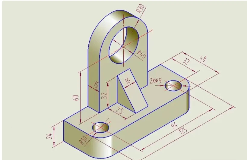
Part Dimensioning
I. Basic Requirements for Dimensioning
1. Correctness: Must comply with relevant national standards.
2. Completeness: Must include all dimensions required for manufacturing the part, without omissions or redundancies.
3. Clarity: Dimension layout must be neat and clear for easy reading.
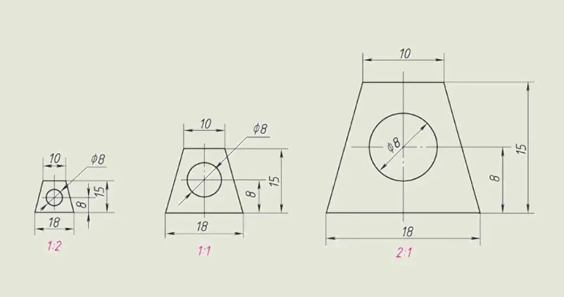
4. Rationality: Dimensions must align with design and manufacturing process requirements.
II. Basic Principles of Dimensioning
1. The actual size of a part is determined by the numerical values indicated on the drawing, independent of the graphical size or the drawing's precision.
Image
Actual Size Principle
2. When dimensions are in millimeters (mm), the unit symbol or name need not be indicated; if other units are used, the corresponding unit symbol or name must be specified.
Image
Unit Principle
3. Dimensions indicated on a drawing represent the final finished size of the part shown; otherwise, additional notes are required.
Image
Completeness Principle
4. Each dimension of a part should generally be indicated only once and placed on the view that most clearly depicts the corresponding feature.
Image
Single-Indication Principle
5. Strive for simplified and rational dimension placement, provided there is no risk of misunderstanding or ambiguity.
III. Elements of Dimensioning
A complete dimension consists of: extension lines, dimension lines, dimension line terminators, and dimension values.
Image
Dimensioning Elements
1. Extension Lines
Image
Extension Line Requirements
Extension lines indicate the extent of the dimension. Regulations regarding extension lines:
A. Drawn using thin continuous lines;
B. Drawn extending from the object's outline, axis, or centerline of symmetry; these lines may also serve directly as extension lines;
C. Extension lines should generally be perpendicular to dimension lines;
D. When dimensioning at points of smooth transition, the outlines must be extended using thin continuous lines, and the extension lines drawn from their intersection point;
E. Extension lines should extend approximately 2–5 mm beyond the dimension line.
2. Dimension lines
Image
Dimension line requirements
A. Must be drawn using thin continuous lines;
B. Must not be drawn as an extension of other drawing lines;
C. Dimension lines for linear dimensions should be parallel to the segment being dimensioned;
D. Intersections between dimension lines, or between dimension lines and extension lines, should be avoided as much as possible;
Image
Reference for dimensioning requirements
3. Dimension line terminal styles
Image
Dimension line terminal styles
4. Dimension numerals
Image
No drawing lines may pass through dimension numerals
Image
Representation of linear dimensions
A. Numerals for linear dimensions are usually placed above the dimension line or within a break in the line;
B. Numerals for angular dimensions must be written horizontally;
C. Dimension numerals must not be crossed by any drawing lines; if this occurs, the drawing line must be broken or the dimension placed via a leader line;
Image
Centerline break
D. Orientation of linear dimension numerals: for horizontal dimensions, the top of the numeral faces up; for vertical dimensions, the top faces left; for inclined dimensions, the top tilts towards the upper side; avoid placing dimensions within the 30° zone.
Image
Points to note
IV. Common dimensioning methods
1. Angular dimensions
(1) The dimension line should be drawn as an arc centered at the vertex of the angle. Extension lines are drawn radially.
(2) Angular dimension numerals are always written horizontally.
Image
Angular dimensions
2. Arc length dimensions
Image
Arc length dimensions
3. Diameter dimensions
(1) When dimensioning a diameter, the symbol φ must be placed before the dimension numeral.
Image
Diameter dimensioning
Image
Reference for diameter dimensioning
(2) When dimensioning a spherical diameter, the symbol S must be placed before the symbol φ. Image
Image
Dimensioning a sphere
4. Radius dimensions
(1) When dimensioning a radius, the symbol R should be placed before the numerical value.
Image
Radius dimensioning
Image
Radius dimensioning
Image
Arc radius dimensioning
Image
Arc radius
(2) The dimension should be placed on the view that shows the arc.
Image
Notes on radius dimensioning
(3) When dimensioning a spherical radius, the symbol S should be placed before the symbol R.
Image
Spherical radius dimensioning
5. Dimensions in confined areas
Image
Dimensions in confined areas
Image
Dots replacing arrowheads
6. Dimensioning method for symmetrical figures
Image
Dimensioning method for symmetrical figures
V. Simplified dimensioning methods
(1) Undercut (tool relief groove)
Image
Undercut
(2) Taper pin hole
Image
Taper pin hole
(3) Square
Image
Square dimensioning method
Use the symbol □ to indicate a square; place it before the numerical value of the side length.
VI. Common symbols and abbreviations for dimensioning
Image
Common symbols and abbreviations for dimensioning
Assignment: Identify and correct errors (zoom in to view the figures)
Image
Assignment (left figure is incorrect; right figure is correct)


