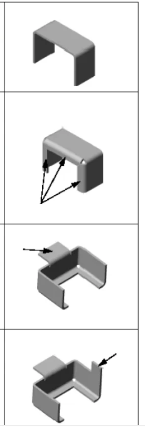
Sheet metal parts are a specialized type of solid model characterized by thin walls and bends. The wall thickness remains uniform throughout the model, and the degree of bending is controlled by specifying a bend radius. Here is a brief overview of some fundamental sheet metal features in SOLIDWORKS. Key commands include "Base Flange," "Miter Flange," "Edge Flange," and "Tab."
I. Base Flange
The Base Flange command creates the base feature for a sheet metal part. It functions similarly to an Extrude feature but incorporates bends based on a specified bend radius. A Base Flange can also be created from a closed-profile sketch to form a flat sheet metal part.
The Base Flange serves as the foundational feature of a sheet metal part; it establishes the initial solid body and defines settings that apply to subsequent sheet metal features.
Image
II. Miter Flange
The Miter Flange feature allows you to add a series of flanges along one or more edges of a sheet metal part. You can apply tangency options where needed to generate mitered joints.
Image
III. Edge Flange
The Edge Flange feature adds a flange to a selected edge of a sheet metal part; both the bend angle and the sketch profile can be modified.
IV. Tab
The Tab feature adds a sheet metal tab of uniform thickness to the part; the sketch for the tab must be created on an existing surface.