


A method for improving the positional accuracy of drilled holes based on Coordinate Measuring Machine (CMM) results is proposed and validated. Through data analysis and practical verification, the hub drilling process is optimized to enhance positional accuracy. By aligning the hub's orientation during CMM inspection with the orientation and sequence used in the machining center's drilling program, the distribution pattern of hole positions is statistically analyzed over multiple measurements to calculate the coordinate offset between the actual drilled center point and the theoretical center point. Experimental validation across multiple batches demonstrates that this method can reduce hub hole positional deviation by up to 31.25%, offering a cost-effective solution to improve the positional accuracy of existing machining centers without the need for equipment upgrades.
Image
01
Introduction
With the development of the axle industry, some manufacturers have imposed increasingly strict requirements for hub hole positional accuracy [1]. In actual production, equipment aging often makes it difficult to ensure that all machine tools meet the positional accuracy specifications defined in the engineering drawings. Relying on specific high-precision machining centers for production can compromise efficiency and increase costs. Conversely, purchasing new machine tools or refurbishing existing ones raises costs; furthermore, since most other products do not require such high positional accuracy, these investments could lead to wasteful expenditure when manufacturing other product lines. To address this, this paper proposes and validates a program compensation method based on measurement feedback. By using a CMM to precisely measure systematic hole position deviations-and subsequently calculating and applying inverse compensation within the machining center's program-it is possible to significantly improve hub hole positional accuracy and increase the product yield rate, thereby meeting the diverse needs of various customers.
Image
02
Machining Case Study
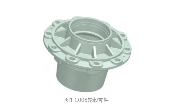
Figure 1 illustrates the C008 hub component produced by a certain company, which requires a positional accuracy of 0.20 mm. While the company's existing equipment can consistently achieve positional accuracy below 0.20 mm-thereby meeting the requirements for this specific product-other customers require a positional accuracy of 0.15 mm for similar products. Such high-precision requirements can currently only be met by a limited number of newly purchased machine tools. However, the production capacity of these machines is essentially saturated, making it difficult to guarantee timely delivery of customer orders, while labor costs associated with their operation are also higher. To enhance the company's overall production capacity and product competitiveness, there is an urgent need to unlock the precision potential of existing equipment through process optimization, thereby meeting stricter customer requirements while controlling machining costs.
[Image]
Figure 1: C008 wheel hub component
This paper presents a comprehensive process experiment aimed at improving the positional accuracy of wheel hub drilling holes. The study follows four key steps-machining, measurement, data correction, and effectiveness verification-to achieve the goal of meeting customer needs while reducing machining costs.
[Image]
03
Identification of Factors Affecting Machining Accuracy
The primary factors influencing the positional accuracy of the C008 wheel hub include tooling, cutting tools, and the machining equipment itself.
1) Tooling is used to align the wheel hub center with the workpiece origin of the machining center. The original setup utilized a mandrel; however, the theoretical maximum clearance between the mandrel and the wheel hub was 0.05 mm, which significantly impacted positional accuracy. To eliminate this positioning error, an innovative pneumatic chuck fixture was designed to replace the mandrel. The selected pneumatic chuck offers a centering accuracy of 0.001 mm, rendering its impact on positional accuracy negligible.
2) As the company standardizes the models and brands of cutting tools used across the board, and given that cutting tools-being standardized components-contribute minimally to systematic deviation, the tool brand remained unchanged throughout the experiment to ensure consistency in experimental variables.
3) The machining centers vary by brand and age depending on when they were purchased. With tooling and cutting tools held constant, the machine tool itself represents the most significant variable affecting machining accuracy-a variable that cannot be altered during the machine's service life. Having controlled or eliminated the variables associated with tooling and cutting tools, the study focuses on addressing the systematic positioning deviation inherent to the machine tool. Conducting the experiment under standard maintenance conditions allows for a more effective validation of the proposed method's feasibility.
[Image]
04
Experimental Method
To ensure the consistency and comparability of measurement data, the C008 wheel hub was maintained at an identical orientation and subjected to the same inspection sequence during both the drilling process at the machining center and the subsequent coordinate measuring machine (CMM) inspection. Personnel are required to strictly adhere to the specified positioning angles, drilling sequences, and inspection orders. This ensures that measurement results can be accurately analyzed and eliminates measurement errors caused by incorrect positioning angles.
4.1 Test Method
CMM (Coordinate Measuring Machine) inspection is time-consuming; excessive sampling creates bottlenecks in the inspection line, hindering the efficiency of routine product inspections [2], while insufficient sampling fails to capture the stability and fluctuations of data during the machining process. To balance inspection efficiency with data reliability, the test utilized small-batch processing runs of three parts each. This approach yielded statistically significant sample data while keeping the inspection cycle manageable, thereby minimizing the impact on standard production schedules.
4.2 Minimizing Variables
Throughout the test, the tooling and machine tool remained unchanged, and the theoretical tool life was set at 150 parts. To ensure consistent test conditions and result comparability, a new tool was installed at the start, and no tool adjustments were made during the first two test runs; this effectively eliminated tool-related variables and ensured the reliability of the data source.
4.3 Inspection Requirements
The C008 wheel hub is a rotational component. During machining, the part's orientation had to comply with the test specifications. Furthermore, the drilling and CMM inspection sequences remained consistent throughout the test to ensure data accuracy, thereby providing a reliable foundation for subsequent error analysis and program compensation calculations.
4.4 Machining Process Control
To maintain strict control over the entire test process, workshop management trained machine operators and quality inspectors according to the test protocols, ensuring a complete understanding of the test plan and workflow. Following the initial CMM inspection of the day, machining and inspection proceeded according to the specified requirements. Dedicated personnel monitored and verified the entire process-from the first part to the last-to guarantee the authenticity and validity of the data. The C008 wheel hub component features a total of 12 holes; the results of the CMM (Coordinate Measuring Machine) positional tolerance inspection [3] for Hole 1 are presented in Table 1. This table reveals the dimensional errors regarding the actual hole's theoretical position in terms of polar radius and polar angle [1]. Based on these values, the machining program can be adjusted in reverse-specifically by modifying the polar radius and polar angle coordinates in the drilling program and setting program compensation values-to verify the feasibility of improving drilling positioning accuracy through this method.
Table 1: CMM positional tolerance inspection results for Hole 1
[Image]
[Image]
05 Machining Trials
Since CMM inspection is time-consuming, an excessive number of samples would cause bottlenecks on the inspection line, while too few samples would fail to verify machining stability; therefore, the test was conducted using batches of three parts. The experiment comprised four batches of three parts each, with the first batch representing the initial machining run. After adjusting the program based on the results of the first batch, the second batch was inspected. If the inspection results for the second batch showed a significant improvement in positional tolerance, the third and fourth batches would be verified after a tool change (performed every two days) to assess the stability of the positional tolerance following the tool change.
5.1 Product Selection
The C008 product was selected, and the tooling fixture was switched to a pneumatic chuck setup, improving centering accuracy to 0.001 mm. The product's positional tolerance requirement is 0.20 mm-a standard achievable by all the company's machine tools. On this basis, the feasibility of stabilizing the positional tolerance to less than 0.15 mm using program compensation was evaluated.
5.2 First Batch Inspection
Following the successful initial inspection, the operator was instructed to machine three parts according to the test requirements and submit them to the Quality Inspection Department's CMM room for testing. Upon completion of the inspection, quality personnel forwarded the reports to the testing team. The positional tolerance inspection results for the first batch of three parts (Nos. 1#–3#) are shown in Figure 2; the positional tolerance for Holes 7, 8, and 12 on some parts exceeded 0.15 mm, with a maximum value of 0.16 mm. Figure 3 illustrates the positional tolerance deviations for the holes in the first batch; where significant deviations occurred, the offset distance and direction of each hole relative to its theoretical position were consistent. Figure
Figure 2: Position tolerance inspection results for the first batch of products (Nos. 1#–3#)
Figure
Figure 3: Hole position tolerance deviation plots for the first batch of products (Nos. 1#–3#)
5.3 Analysis of position tolerance measurement results
Table 2 presents the statistical analysis of the inspection results for Hole 7, comparing the actual values and average values obtained via CMM (Coordinate Measuring Machine) against the programmed values from the machining center [4].
Table 2: Statistical analysis of inspection results for Hole 7
Figure
5.4 Adjustment of programmed values
As shown in Table 2, the average actual error in polar radius for Hole 7 is 0.062 mm, and the error in polar angle is -0.004°. The machining program coordinates for Hole 7 were adjusted to a polar radius of 167.562 mm and a polar angle of 215.996°. The same analysis method was applied to the remaining holes to determine error patterns and optimize the machining program through compensation [5].
5.5 Position tolerance measurement results for the second batch
After the optimized program was adjusted and renamed by the testing personnel, it was imported into the machining center's CNC system, and the new program was used for machining. To prevent batch scrapping due to potential program issues, the original program was reverted to after the new program passed the initial inspection and two additional parts were machined.
Figure 4 shows the position tolerance inspection results for the second batch of three products (Nos. 4#–6#), and Figure 5 shows the hole position tolerance deviation plots. The maximum position tolerance value dropped significantly from the original 0.16 mm to 0.11 mm-a reduction of 31.25%. This highly significant optimization effect fully validates the effectiveness of the program compensation strategy. Figure
Figure 4: Position tolerance inspection results for the second batch of products (Nos. 4#–6#)
Figure
Figure 5: Hole position tolerance deviation plots for the second batch of products (Nos. 4#–6#)
5.6 Position tolerance measurement results for the third and fourth batches
To systematically verify the feasibility and stability of this program-based compensation method and to ensure machining quality, operators were required to change tools according to the test protocol and conduct machining trials for the third and fourth batches (Nos. 7#–12#) at specified intervals. The position tolerance inspection results are shown in Figure 6; the maximum position tolerance remained consistently below 0.11 mm. This demonstrates that the method maintains reliable improvements in position tolerance accuracy even after tool changes, exhibiting good repeatability and practicality.
Figure
Figure 6: Position tolerance inspection results for the third and fourth batches (Nos. 7#–12#)
Figure
06
Conclusion
This paper presents a method for improving the drilling position tolerance accuracy of machining centers based on coordinate measuring machine (CMM) inspection and program-based compensation. Through systematic machining and measurement of actual hole coordinate data-validated across multiple test batches-the method analyzes systematic deviations from theoretical positions and corrects the coordinate values of relevant holes in the CNC program, thereby implementing reverse coordinate compensation. This method can reduce the maximum position tolerance deviation of hub holes by up to 31.25% with stable and reliable results. It significantly enhances the machining quality of existing equipment without requiring upgrades to machine tools or cutting tools, thereby maintaining production efficiency for standard products while avoiding the increased costs associated with acquiring new equipment. The method is primarily suitable for optimizing the position tolerance of rotational parts, offering excellent cost-effectiveness and ease of implementation; however, its applicability to asymmetrical or structurally complex parts requires further study. This method can be adopted for similar products and processes, helping to boost the market competitiveness of the enterprise's products.


